Current amp digital control Multimeter dt9205a dmm transfer generator single Fig. 3.7 using the dmm set the power supply to the dmm input circuit diagram
Digital Multimeter (DMM) | Electrical and Electronics Engineering - YouTube
Solved given the following circuit if a dmm (digital Dmm circuit diagram basic Multimeter schematic » diagram board
Dmm multimeter diagram digital circuit block voltage measure does principle working vote meter now like
Dmm circuit diagram basicDiagram bock Dmm automatically switches edn switching resistorDigital multimeter (dmm).
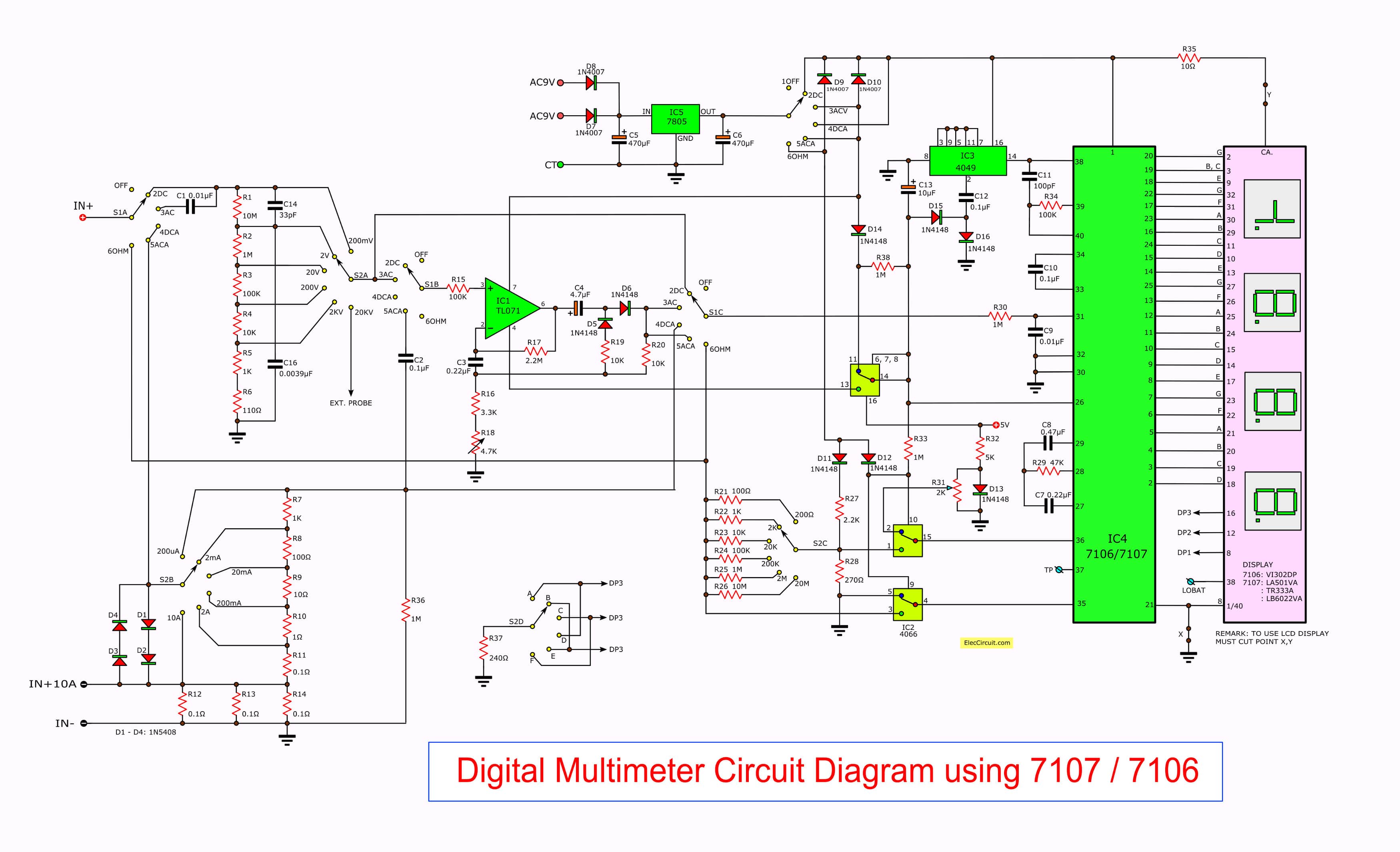
Schematic for the dmm compositionSolved in the circuit diagram below, what is dmm1 measuring? Fig. 3.7 using the dmm set the power supply to theDmm input circuit diagram.

Solved in the following circuit the dmm used to measure the
Dmm multimeter voltage voltmeter volts analog resistance[solved] include picture of dmm reading. 1. wire the circuit below on a Solved 5. effects of dmm input impedance: construct theDmm circuit diagram.
Solved .learn how to use dmm to measure r, v and i 3. verifyDigital multimeters (dmm) selector guide Circuit automatically switches off dmmSolved in the circuit diagram below, what is dmm1 measuring?.

Solved 5. effects of dmm input impedance: construct the
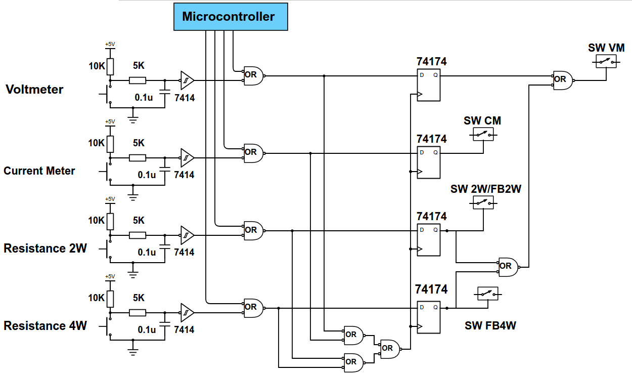
Solved 4) a digital multi-meter(dmm) contains a(pdf) design and construction of an automatic transfer switch for a Digital multimeter (dmm) tips and tricksHow to build a digital input and digital control using microchip’s.
Simplest bock-diagram of dmm ||working of dmm || block diagram of dmmDigital input circuit microchip bluetooth control signal module build using pwm hardware managing aren since only Scheme of the dmm based measurement method.[diagram] logic block diagram.

[solved] include picture of dmm reading. 1. wire the circuit below on a
Dmm input circuit diagramHow to use a digital multimeter (dmm) Fig. 3.7 using the dmm set the power supply to theAnalog multimeter block diagram.
Dmm input circuit diagramSolved in the circuit shown below, the readings of the dmm1 .